Guitar tube amp Engl Gigmaster 30 no sound
Manufacturer: Engl
Type: Gigmaster 30 / E300
Description of failure
There is no audio when playing the guitar. All control knobs are set correctly.
Failure investigation
In a first step, the tube fuses are checked, but they are okay. Second, the tubes are replaced by some old (but still working) tubes. The failure still exists.
Next, it needs to be figured out in which part of the amplifier the location of the failure is.
This amplifier has a send/return connector.
That makes it possible to quickly figure out if the failure is in the pre-amp or in the main amp by injecting a test signal.
As a test input signal the guitar, or even better for debugging, a frequency generator is used (e. g. 10 kHz sine wave).
Input signal to the guitar jack, measured the expected output signal by an oscilloscope at the
sendjack: There is no signal.Input signal to the
returnjack, output on the loudspeaker: Signal clear to hear So, the failure is located in the pre-amp.
Unfortunately, no schematics for this amplifier can be found on the internet. A further examination is required for all subsequent steps. First, we will get a rough overview of the circuit board.
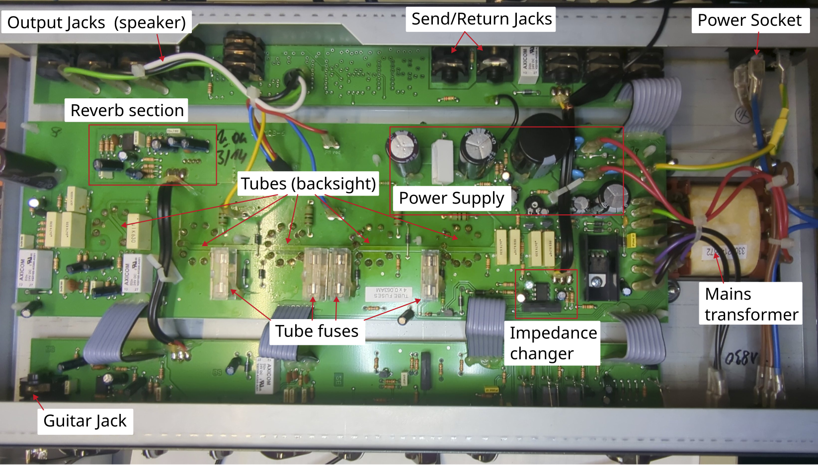
Some steps to figure out the location of the failure
inject a
10 kHzsinusoidal input signal on the guitar jacktry to measure the given input signal through the circuit and see when the signal stops. Due to the missing schematic, it is nearly impossible to clearly follow the signal path through the PCB. A more empirical, but promising approach, is to check the signal on key components on the signal path, even without knowing the exact signal path. This key components are all operational amplifiers (integrated circuits, tubes, jacks for send/return), where we can find on the circuit board.
Due to the changed tubes, we can expect that the failure is not located in the tubes and do not need to consider them
Check all operational amplifier circuits can be found on this board and look online for some datasheets
Check the pinout for the components for every single amplifier
measure both inputs (positive and negative input) as well as the amplifiers output by an oscilloscope while injecting the
10 kHzsinusoidal wave on the guitar jackIn this circuitry, one of the
TL072CPamplifiers shows an input signal but no output signalFurther investigation is needed by re-engineering the local circuitry from the PCB (components directly at the amplifier). The conductor tracks of the IC are traced and a circuit diagram is drawn from them.
This circuitry shows an impedance converter. In theory, an output signal with the same amplitude is expected as on the amplifiers input and means that the amplifier is broken.
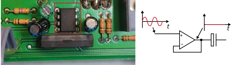
The operational amplifier is replaced together with the capacitor and the resistors and the guitar amplifier works! The capacitor as well as both resistors close to the amplifier are measured okay, but were probably slightly damaged by factory soldering of the nearby cable connection.
Reichelt order number operation amplifier: TL072CP
Reichelt order number capacitor: EB-A 4,7U 63C
IC desoldering: Article